Somewhere on the screen is Earth. You can point to it. How could a program find it again after it has drawn it? Give Earth an address on a grid and a color number you can read back.
Mark two landing sites
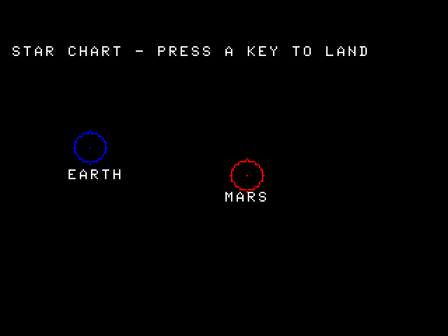
Choose RGB under Settings → Video Signal. Run CHART.bas. Leave it waiting for a key. Look for a blue ring labeled EARTH and a red ring labeled MARS. Each ring has a tiny dot in the center. Press A after you have found both dots.
The guest star chart labels a blue circle Earth and a red circle Mars. Each circle has a center marker.
The program reports EARTH MARKER 1 and MARS MARKER 2. Those numbers came from the dots, not the names. You could tell the planets apart from the labels even when the two colors were hard to distinguish.
40 HSCREEN 2:HCLS 0
42 PALETTE 0,0:PALETTE 1,9:PALETTE 2,36:PALETTE 3,63
45 HCOLOR 3:HPRINT(1,1),"STAR CHART - PRESS A KEY TO LAND"
50 FOR I=1 TO 2
60 HCIRCLE(X(I),Y(I)),12,I
70 HSET(X(I),Y(I),I)
75 HPRINT(INT(X(I)/8)-2,INT(Y(I)/8)+2),P$(I)
80 NEXT I
90 A=HPOINT(X(1),Y(1)):B=HPOINT(X(2),Y(2))
HSCREEN 2 opens a CoCo 3 graphics screen. HCLS 0 fills it with color slot zero. Think of a palette as numbered pots of paint. Line 42 puts black in pot 0, blue in 1, red in 2 and white in 3 for our RGB display. The number stored at Earth’s center is 1, even though the RGB color chosen for pot 1 is 9. This distinction explains the report at the end.
HCIRCLE draws the rim. HSET colors the pixel at the center. HPOINT asks the screen which pot that pixel uses. The coordinate pairs came from the chart data. HPRINT places whole letters on its own grid: line 75 divides each pixel coordinate by eight, drops the fraction, and shifts the label underneath the ring. A letter covers a little block of pixels.
Keep a second picture ready
Earlier BASIC programs could draw on a coarse SET grid or use PMODE graphics. A PMODE program can keep more than one picture in RAM. Book 2’s stripe experiment shows what one of those pictures looks like through composite and RGB. Here we will change which picture the monitor sees.
Run PAGES.bas in Disk BASIC. It first selects the 32-column screen so the following legacy graphics commands start in the intended display mode. Wait for the square at the left. Tap A once and find a smaller square on the right. Tap it again and the first square returns. A third tap brings you back to 40-column text.
The first PMODE picture shows a filled square at the left. The other picture has already been drawn in memory.After the first keypress a smaller square appears on the right. The previous square is still on the other page.
5 WIDTH 32:CLS
10 PMODE 1,1:PCLS 0:SCREEN 1,0
20 COLOR 1,0:LINE(16,16)-(95,95),PSET,BF
30 PMODE 1,3:PCLS 0:COLOR 3,0
40 LINE(160,64)-(223,127),PSET,BF
50 IF INKEY$="" THEN 50
60 SCREEN 1,0
70 IF INKEY$="" THEN 70
80 PMODE 1,1:SCREEN 1,0
90 IF INKEY$="" THEN 90
Look closely at lines 30 and 40. BASIC has switched its drawing to another part of RAM before that first keypress. The monitor keeps showing the first square while the second is being drawn. Line 60 is the handoff: SCREEN shows the page BASIC has selected. Line 80 selects and shows the first one again, without drawing its square a second time. This is one way an animation can have its next picture ready in time.
Look behind the visible picture
For a closer look, put a BASIC breakpoint on line 50 of PAGES and run it again. At the stop, leave the CoCo paused. Open the Debugger and choose Graphics Preview.
Choose Current Video Page. The left square is on display.
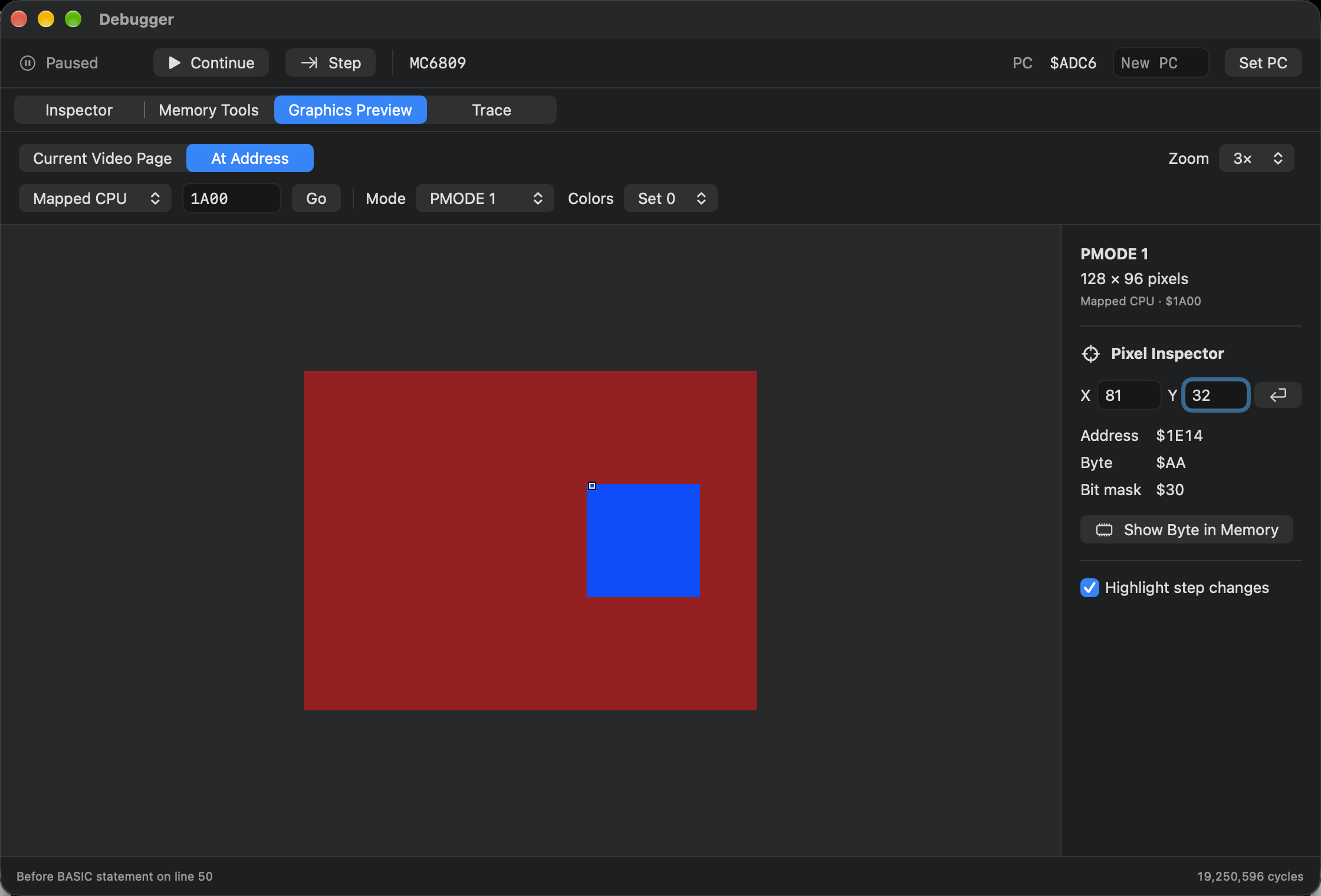
Choose At Address, Mapped CPU, enter 1A00 in the hexadecimal address field and choose Go. Select PMODE 1, Set 0. The square on the right is already there.
In Pixel Inspector, look at X 81, Y 32. The byte is $AA at $1E14. You can leave its value alone. This is one byte helping hold the second picture before anyone can see it on the CoCo monitor.
The native Graphics Preview inspects the right-hand square at mapped address 1A00. Pixel 81,32 uses two bits of the byte at 1E14.
Why page starts 1 and 3? One PMODE 1 picture needs two of BASIC’s graphics allocation pages. The first uses pages 1 and 2; the second starts at 3. The address above applies to the Disk BASIC setup in this exercise. The preview shows its 128 by 96 stored pixels. BASIC’s drawing coordinates cover a finer grid, so the preview pixel numbers differ from the coordinates in the LINE statement.
Remove the line 50 breakpoint in BASIC Development, choose Continue, and use the three keypresses to finish the trip. You have seen two jobs that a single block of memory can do in succession: hold a drawing under construction, then supply the image on the monitor.
Search this book
Find matching sections in this book. This search runs in your browser; every keyword must match.